Worlds Most Useless Machine Build - Part 6
Building My Own Version of "The World's Most Useless Machine"
Part 6 - Building The Final Prototype
Part 6 - Building The Final Prototype
 I actually finished building my final working prototype just before we got knocked off-line last weekend with our crazy wind store. A week later and with a brand new wicked fast ASUS computer my lovely wife Louise bought me I finally has some time to take and edit up some photos of the box. I must admit I am really anxious now to build my first for sale machine now that I seem to have most of the kinks worked out.
Here is a video and slide show I made showing the final prototype.
I had a heck of time figuring out how to make the arm reliably close the micro switch to turn itself off. My original idea was to mount the micros switch on a an arm off the servo motor mount. That idea was fine but the idea of placing on the side between the mount and the battery holder was bad because the arm tended to bounce off the mount and open the switch instead of just settling in the off position. The solution was pretty simple to just move in on the other side of the mount so I was using the shorter length of the arm to hit the switch which naturally has less movement. Now if the slop of system allows the arm to bounce a bit where the switch is hitting doesn't have enough movement to cause the switch to re-open. Well it worked and the box works very well now! I know the wiring looks a mess. I build the proto circuit on plain perfboard and point to point wired it which took forever to build. My production version will be made on a strip board and will hopefully come out a lot more neat looking.
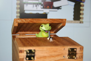
In case you are wondering the smiley friendly snake is a finger puppet my wife had from her soap making supplies. I think it looked funny and it worked out perfectly. She has a number of other finger puppets that would work as well so I will be able to customize the look.
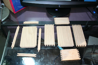
 I all the pieces to size on my table saw using the rip fence and my crosscut jig. I then used my Incra Router jig to make the finger joints and route the dato slots to hold the bottom and top panels. I realized while working on my SketchUp plan I had to make the lid pieces longer than the box to compensate for the saw kerf in the 45 degree split I need cut on the table saw. Another great example of designing in a 3D model before you actually cut wood to save time and money! So that made it a bit more difficult to make rather than the standard way of building the box with the top and bottom attached then to saw off the lid. I ended up in making the lid just a tad too short. My next build I will make it longer realizing I can easily sand it down to the proper length after I cut the split.
In case you are wondering the smiley friendly snake is a finger puppet my wife had from her soap making supplies. I think it looked funny and it worked out perfectly. She has a number of other finger puppets that would work as well so I will be able to customize the look.
 I all the pieces to size on my table saw using the rip fence and my crosscut jig. I then used my Incra Router jig to make the finger joints and route the dato slots to hold the bottom and top panels. I realized while working on my SketchUp plan I had to make the lid pieces longer than the box to compensate for the saw kerf in the 45 degree split I need cut on the table saw. Another great example of designing in a 3D model before you actually cut wood to save time and money! So that made it a bit more difficult to make rather than the standard way of building the box with the top and bottom attached then to saw off the lid. I ended up in making the lid just a tad too short. My next build I will make it longer realizing I can easily sand it down to the proper length after I cut the split.
You can see the extra length added to the lid on this plan. I will also need to add some height to the box by one finger joint when I build my production model because the space between the servo motor mounts and the battery holder was really tight.
I struggles with how to hold down the access lid a bit until I figured I would just a magnet embedded in the bottom with a metal screw coming down from the lid top. I can fine adjust the screw head till it just hits the magnet and grips down firmly holding the lid quite nicely down. It takes a good amount of force to actually open the lid when you need access to adjust the delay or change the batteries.
So now it's time to work on the production model. I need to make a compact reliable circuit board, make the box a tad bigger to fit all the components nicely and make sure I get my hinges placed properly. My obsession continues!!!
So now it's time to work on the production model. I need to make a compact reliable circuit board, make the box a tad bigger to fit all the components nicely and make sure I get my hinges placed properly. My obsession continues!!!


Comments
My name is Zoltan, I live in Hungary. Please refer to, but I speak only a little English.
I really liked the machine unusable, which is waiting for a bit before you come into play. If you please share with me a lot this Schematic? (555 timer)
Thank you and wish you good health!